Pages
- A RULE-BASED TOPOLOGICAL MODELER GENERATOR
- Inference of topological operations: illustration in geology
- Japhy : une plate-forme mécanique et topologique utilisant un langage à base de règles pour l’animation physique.
- JerboaEclatement
- Joptop – Jerboa Optimisation Topologique
- Lesson 1: Discover topological structures of Jerboa
- Lesson 2: Discover embeddings and orbits
- Lesson 3: Modify and write a first rule
- Lesson 4: Write embedding expressions
- Lesson 5: Design topological transformations
- Lesson 6: Utilize the execution cycle of rules
- Lesson 7 : Write scripts in Jerboa
- Lesson 8: Create your own modeler
- Model reevaluation based on graph transformation rules
- Topological inference for subdivision schemes
In this lesson you will learn how to transform the topological structure of an object by creating a graph in the right pattern of a rule. You will be using the same modeler as for all the previous lessons.
SIMPLE TRANSFORMATION OF TOPOLOGICAL STRUCTURES
You are going to learn how the left and right patterns are used to effectively match and transform topological structures of objects. You will write a rule which subdivides an edge into edges by adding a vertex in the middle in two different ways, the first will have left and right patterns with each node matching one dart of the object which is to be transformed and the following will have less nodes which match an orbit.
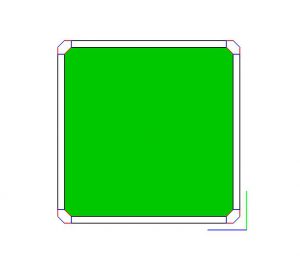
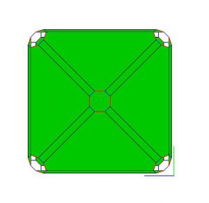
Screens 5.1 and 5.2 show you what the resulting operation will do to the edge of a square.

- open the editor and create a new rule called « SubdivideEdge1 »
- edit the left pattern to match the edge to be subdivided (see Screen 5.1)
- in the left pattern place four nodes which correspond to the four darts of an edge
- make one of those nodes a hook (it doesn’t matter which one)
- place the appropriate links which you would find in an edge (2-link between two nodes at the same end of the edge and 0-link between two nodes which are at opposite ends
- put a 3-link loop on each node
We’re using a 3-loop to specify that the node is it’s own neighbor along the 3-link. In other words the selected edge belongs to two border faces.
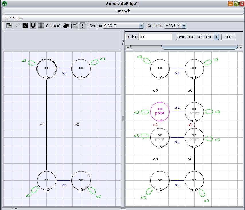
- edit the right pattern of the subdivided edge (see Screen 5.2)
- repeat all of these steps in the right pattern but do not place the 0-links
- place four more nodes between the other nodes, two on each side, these nodes correspond to the four darts of the added vertex in the edge
- these four nodes must be connected with 2-links just like the others and 1-links in the other axis to link the two new edges
- connect the four original nodes to the four new ones with 0-links, each original node connected to the closest new node
You should see patterns that resemble Screen 5.3.
Now you will need to write the point embedding expression for the four nodes of the added vertex. You will only need to write it into one of the nodes and it will automatically be propagated to all nodes which are in the orbit of the point embedding (the vertex <1,2,3> orbit).
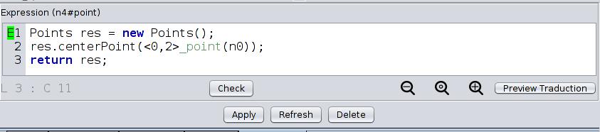
- edit the point embedding expression for any of the four center nodes (see Screen 5.4)
- create a new instance of « Points »
- apply the « public void centerPoint() » method found in the « Points.java » embedding class to this new point with the argument being the two points obtained from n0 and n2
- return the point
- apply, save and export
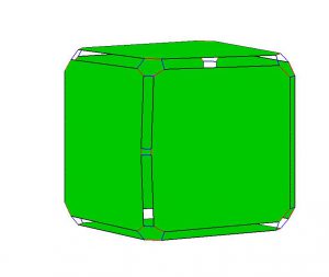
- try your new operation on an outside edge of the TwoCubes object
- try your rule on an edge which belongs to only one face of the TwoCubes object (for example from dart 34)
The pattern matching will fail because the left pattern of the rule does not allow for edges which belong to only one face to be matched.
Now you will make the rule more general by creating nodes which match an orbit of the object. This is done by giving the nodes an orbit , from one dart. Doing this will look like folding the left and right patterns in half.
- open the editor and create a new rule called SubdivideEdge2
- create two nodes in the left pattern connected by a 0-link
These nodes each replace two nodes in the first version so all of the information needs to be transcribed in this version, to do this you will have to observe which links are being deleted and add them to the orbit of the nodes, these are called implicit links.
- write the <α2> orbit into the nodes and place a 3-loop on them
- place two nodes in the right pattern corresponding to the two in the left pattern
- write the <α2> orbit into the nodes and place a 3-loop on them
These two nodes « n0 » and « n1 » correspond to the nodes in the left pattern.
- place two more nodes in line between the two first nodes
- write the <α2> orbit into the nodes, place a 3-loop on them and connect them with a 1-link
These nodes correspond to the four darts you wish to add to the object, replacing the four nodes from the first version.
- connect them to the two first nodes with 0-links
You should have a left and right pattern that look like the ones from the first version folded in half (see Screen 5.5).
Now you will need to write the point embedding expression for the two nodes of the added vertex.
- edit the point embedding expression for any of the two center nodes (see Screen 5.4) to be the same as in the first version
- apply, save and try the operation on the inside edge and the edge on one single face of the TwoCubes and then on an edge between the two cubes
You will notice that the pattern matching fails so the operation will not be applied to the inside edge because the darts of this edge have 3-links which are not accounted for in the rule.
Now you will go one step further and fold the patterns again in the other direction. To do so, you will delete and rename the matched 0-links (see Screen 5.7). You will also delete the 3-loops and include 3-links as implicit links in the nodes.
In the orbit of a node, when the αj link of a node replaces the αi link of a hook node, all matched i-links are renamed to j-links in the orbit of the matched node.
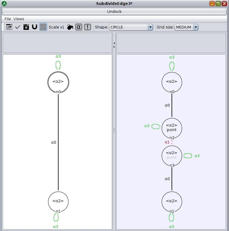
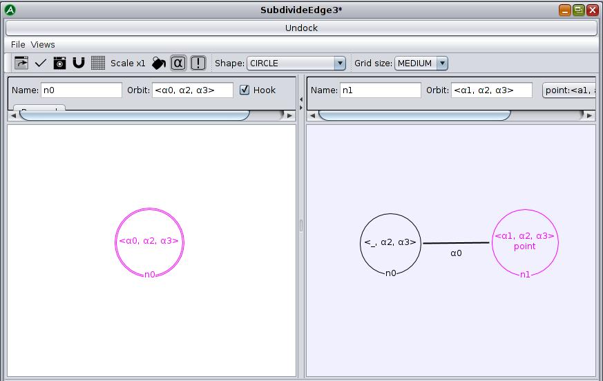
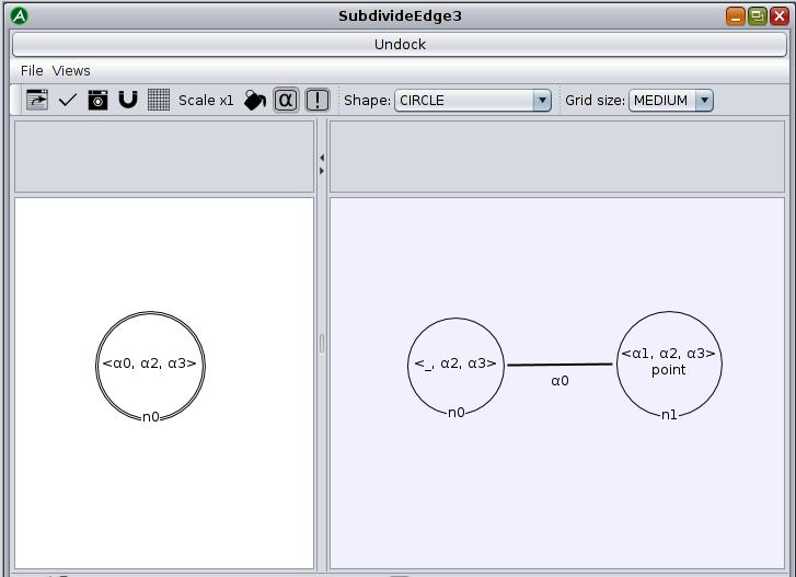
- open the editor and create a new rule called SubdivideEdge3 (see Screen 5.7)
- create a node in the left pattern, write in the <α0,α2,α3> orbit to match any edge
- create two nodes in the right pattern corresponding respectively to the matched vertexes and the added one
- connect the two nodes with a 0-link
- delete 0-links of the matched edge, by replacing the α0 of the left matching node by « _ » in the same node on the right
- rename 0-links of the matched edges 1-links in the created vertex by replacing the α0 of the left matching node by α1 in the new right node
- edit the point embedding expression for any of the center node (see Screen 5.4) to be the same as in the first and second versions
- apply, save and try the operation on the same edges of the TwoCubes
You should now be able to subdivide an inside edge because the 3-link is implicit to the node in the left pattern of the rule and can match all 3-links (loop or not).
MORE ADVANCED TRANSFORMATIONS
You will now create a rule which places a vertex in the center of a face thus subdividing the face, this is called triangulation.
Here is a breakdown of the transformation.
- open the editor and create a new rule called TriangulateFace
- in the left pattern (see Screen 5.10) create a single hook with the face orbit <α0,α1,α3>
Screen 5.10: Left pattern
- in the right pattern, place the same node as in the left pattern, deleting the 1-link to separate the edges from the matched face
- create a new node n2 in the right pattern with the renamed orbit from the node in the left pattern which creates the dual vertex in the center of the triangulated face with the same structure as the face (0-links are renamed to 1-links and 1-links are renamed to 2-links)
- create a new node n1 in between the two other nodes to create the bases of the added edges between the original darts of the face and those of the central vertex
Where darts of the face matched by n0 are linked by 0-links, darts created by n1 are not linked so « _ » replaces α1 in the orbit. Where darts of the face matched by n0 are linked by 1-links, darts created by n1 are linked by 2-links so n1 will have the orbit <_,α2,α3>.
- the darts of the face must be linked to the new darts at the base of the edges leading to the center by 1-links and the darts at the base of the edge must be linked to the darts in the center by 0-links
- select the third dart of the right pattern, select the point embedding (see Screen 5.11) and edit it
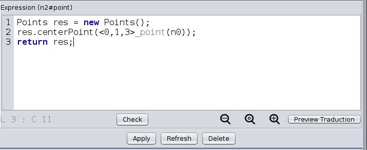
- create a new instance of Points
- give it the coordinates corresponding to the center of a list of points with the « public void centerPoint(java.util.List<Points> list) » method found in the « Points.java » embedding class
In this case you want the center of the face so you will create a list of all the darts of the face by indicating the orbit and the first dart (the hook in this case): « <α0,α1,α3>_point(n0) ».
- finally, return the instance of Points, apply, save and export
- refresh the project and launch the viewer so you can test your rule on any object.
MULTIPLE HOOKS
In the first lesson you used a rule called « Sew3 » for which you had to select two darts to apply it. You will now rewrite the Sew3 rule yourself to see how to write a rule with more than one hook.
- open the editor and create a new rule called NewSew3 (see Screen 5.12)
- place two nodes in the left pattern which should each match a volume face (so with the <α0,α1> orbit) and make them hooks
- place 3-loops on these nodes to match free faces in the 3rd dimension
- place the same two nodes in the right pattern and connect them with a 3-link instead of placing the 3-loops
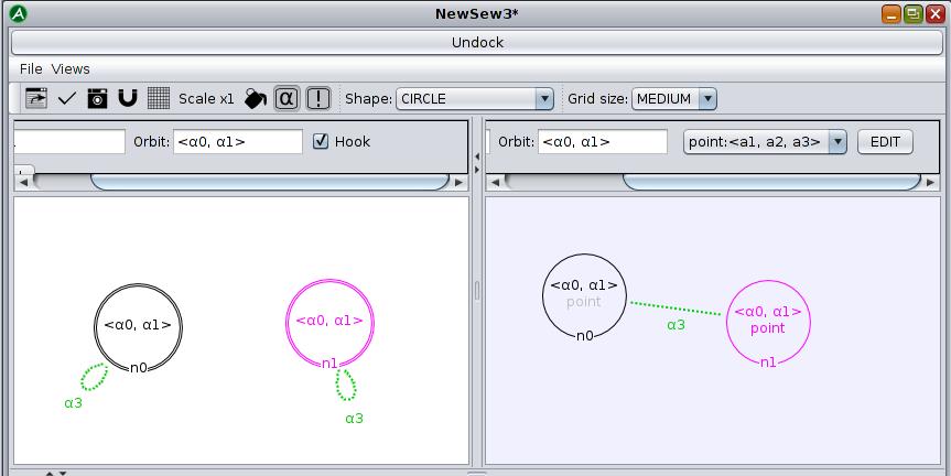
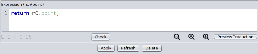
If two volume-faces are to be connected with 3-links to form a new face they must have the same position so, in case this is not the case before applying the operation, you must edit the point embedding of one of the nodes in the right pattern to make sure both volume-faces are in the same place.
- edit the point embedding of one of the two nodes in the right pattern so that the point embedding of that node has the same value as the point embedding of the other node (see Screen 5.13)
NO HOOKS
You will now create a rule which creates a square out of nothing, without any hooks and without a left pattern.
- open the editor and create a new rule called « CreateSquare » (see Screen 5.14)
- place all eight nodes in the right pattern which are needed for a square and the appropriate links and loops
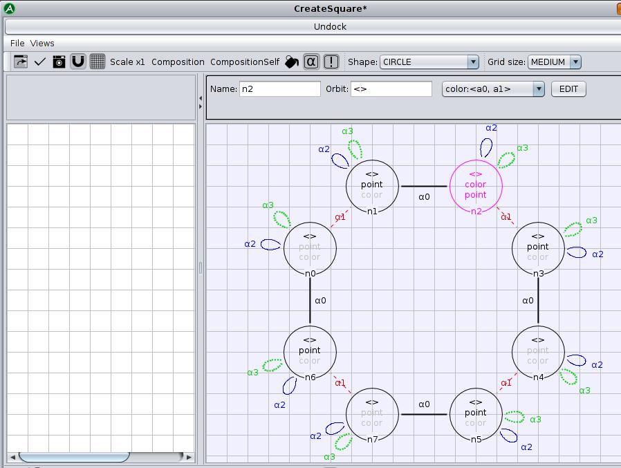
- return an instance of Points for one node of each vertex in order to make a square
- add a color to one of the nodes of the right pattern
- apply, save and export the rule to try it in the modeler
What have you learned ?
- What is the difference between implicit and explicit links in the pattern of a rule?
- How many darts are added when triangulating a triangular face?
- How do you delete an implicit link?