Pages
- A RULE-BASED TOPOLOGICAL MODELER GENERATOR
- Inference of topological operations: illustration in geology
- Japhy : une plate-forme mécanique et topologique utilisant un langage à base de règles pour l’animation physique.
- JerboaEclatement
- Joptop – Jerboa Optimisation Topologique
- Lesson 1: Discover topological structures of Jerboa
- Lesson 2: Discover embeddings and orbits
- Lesson 3: Modify and write a first rule
- Lesson 4: Write embedding expressions
- Lesson 5: Design topological transformations
- Lesson 6: Utilize the execution cycle of rules
- Lesson 7 : Write scripts in Jerboa
- Lesson 8: Create your own modeler
- Model reevaluation based on graph transformation rules
- Topological inference for subdivision schemes
To complete this tutorial you will need to understand how geometric objects are represented and how topological structures work because it is the central notion to using Jerboa to build a geometric modeler. In this lesson you will be using and completing a 3-dimensionnal example modeler made with Jerboa.
For the first two lessons you will use a runnable .Jar file of a modeler developed in Jerboa which you can download here, later on you will install Jerboa so as to modify this modeler.
You may have to set the rights to the jar file (with a « chmod 755 » in the terminal if you are using linux).
UNDERSTANDING THE TOPOLOGICAL STRUCTURE OF AN OBJECT
The operations which are specific to this lesson can be found in the Lesson1 folder.
- execute the « Practice.jar » file
- you should see the modeler open
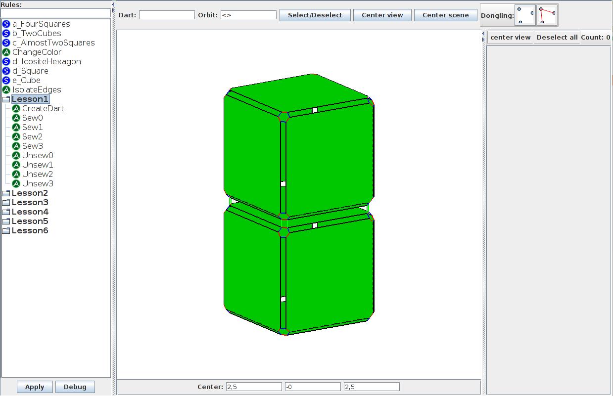
- select and apply the “a_TwoCubes” builder to create a simple object (see Screen 1.1) and click on the « Center scene » button
The central part of the screen is dedicated to the 3-dimensionnal representation of objects and scenes. You can use the right click to move the point of view and the scroll wheel to zoom in and out.
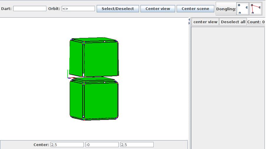
- switch between the exploded (see Screen 1.2) and geometrical (see Screen 1.3) views of the object in the view menu and move around the object to observe the differences between the two views
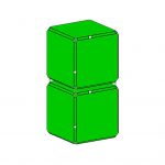
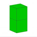
Notice that the exploded view shows 12 nodes in each corner where the two cubes meet as opposed to the single vertex in the geometrical view.
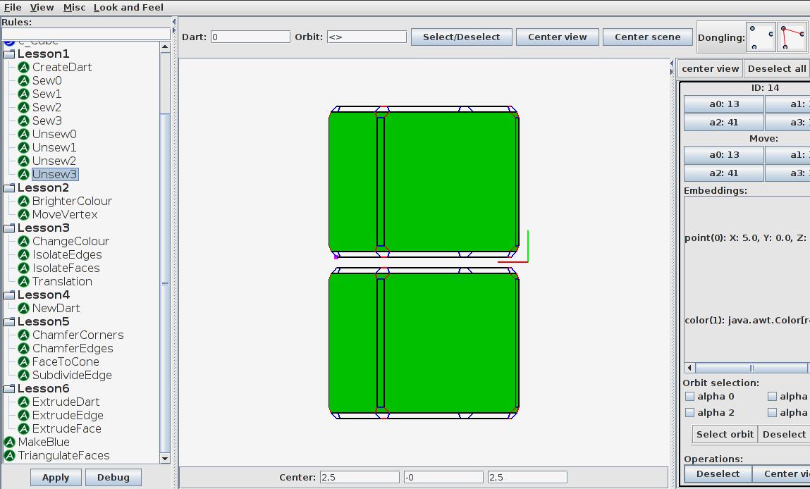
Just above the center you will find the “dart selection tool” which enables you to select any existing dart with its identifying number. You can also select one or more darts using the mouse click but for accuracy reasons, whenever you need to select a particular dart, you will be prompted to do so using this tool. Note that you may have to deselect previously selected darts using the « Deselect all » button on the right of the screen.
- type 14 into the « Dart: » text field and click on « Select/Deselect »
- find the selected dart
You will notice that the window to the right of the screen now shows information about the selected dart.
You can navigate from one dart to the next along a chosen link by clicking on the appropriate link under the « Move » label. Don’t worry about the rest of the window, we’ll get back to that later. The two cubes are linked together with links of the 3rd dimension (here called 3-links). You can observe that dart 6 (which is part of the other cube) is adjacent to dart 14 along the 3-link. You will notice that dart 44 is adjacent to itself along the 3-link, this is because there is no dart connected to it with this specific link so the link becomes a « loop ». Notice that the darts, being displayed as infinitely small, are now invisible, you can select them with the dart selection tool to see them highlighted in pink. If you go to « view » and select « show dot » you will be able to see every dart even if it is not connected to anything.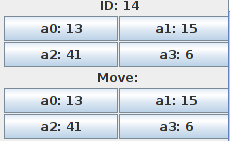
DECONSTRUCTING AN OBJECT
BUILDING AN OBJECT
- use the dart selection tool to select darts “11” and “26”
- execute the “Sew2” rule
- repeat with darts « 12 » and « 31 », « 14 » and « 41 », « 9 » and « 51 » remembering to deselect previously selected darts
- connect the two cubes with 3-links
- select darts “0” and “8”
- execute the “Sew3” rule, you should have two connected cubes
TOPOLOGICAL CONSTRAINTS
1- The graph is non-oriented which means that the links don’t have a direction. 2- Each dart has exactly n+1 links, one of each dimension from 0 to the topological dimension n (in our 3D modeler the dimensions of the links go from 0 to 3). 3- For each instance of i and j, where 0<=i<=i+2<=j<=n (n being the dimension of the graph), each dart must have an « i-j-i-j » cycle of links, which means that successively navigating along the links of dimensions i, j, i and j will lead back to the initial dart (even if some links are loops). Three link cycles must exist for each node on a 3-dimensional graph. These cycles are 0202, 0303 and 1313. Two faces which are connected by a common corner are thus impossible to represent with a G-map and cannot be built with Jerboa.
- select any dart on an object and make sure it has four different links (a0, a1, a2 and a3)
- move along the same link twice and make sure you get back to the original dart
- navigate along the four links of a cycle and make sure you get back to the original dart
What have you learned?
- Does a graph represent the geometric shape of an object?
- How many darts are needed to create a square?
- Which color is the link for the 2nd topological dimension ?